MIT LEG LAB BIPED JOURNAL. began on 04.99 and backdated some...
| 05.30.99 |
|
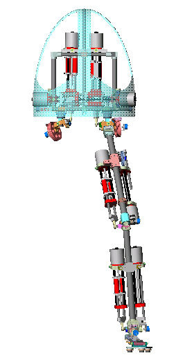
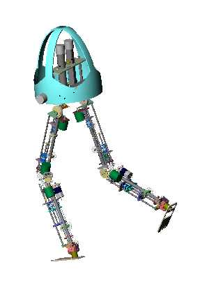
| A CAD model of the entire biped(minus a leg of
course) and a close-up of the upper body without the shell. There are simplified actuators in the assembly. All degrees of freedom
have fully defined actuation schemes with limit stops. The electronics are
missing and the shell interferes a bit with the yaw actuators. As well, the
exact mechanism for attaching the external frame to the internal frame is
uncertain. This assembly is completely independant from the 10.98 assembly. The
only pieces they share are carbon fiber tubes.
|
| 04.10.99 |
|
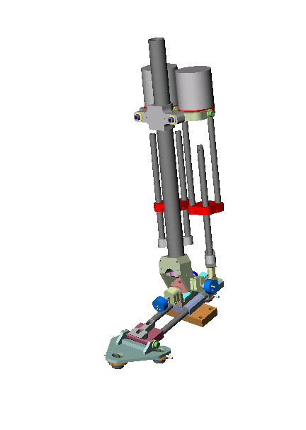
| A CAD model of the biped thigh and hip. There are two
simplified FrAP's in the assembly which drive the hip pitch and knee
pitch. The hip pitch is a cable system and the knee pitch is a direct
attachment drive system with a rodend. The knee pitch actuator is mounted on a
pivot and the hip pitch actuator is fixed to the thigh frame. The hip assembly
includes limit stops for pitch and roll. It also includes an off-the-shelf
double pack angular contact bearing mount which attaches the leg to the body.
|
| 01.25.99 |
|
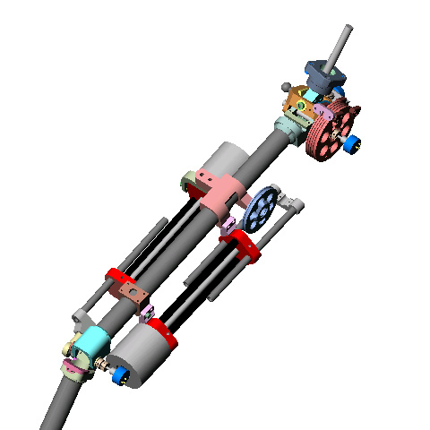
| A CAD model of the biped shin and foot. As
opposed to the Leg-uator design, these actuators are self contained and do not
share structure with the robot leg. The actuators are mounted by a universal
joint on the shin and attached to the foot below the ankle with a ball and
socket(a rod-end) Driving the actuators together actuates
ankle pitch and driving them in opposite direction creates ankle roll. The six
axis force sensor has been replaced by four single axis load cells as mentioned
in the previous foot prototype. A more detailed picture of the FrAP can be
found on the main biped page. |
| 11.98 |
|
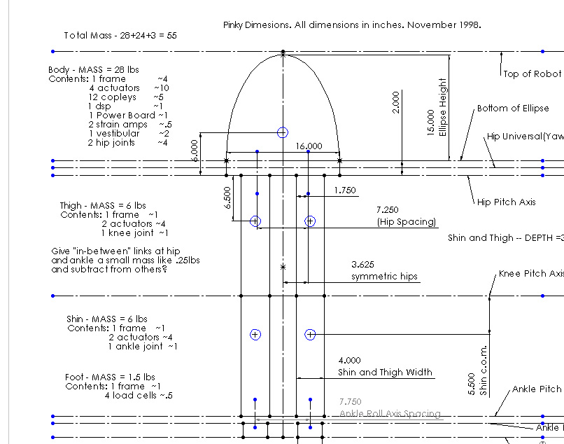
| Preliminary size and weight
specifications used for early M2 computer simulations and for keeping designers
in check. The specifications are based on preliminary actuator weight
estimates. Each actuator is about 2.5 lbs. The link lengths are based on those
of a 50th percentile US male. If the JPG is not readable, try this .tif.
|
| 11.07.98 |
|
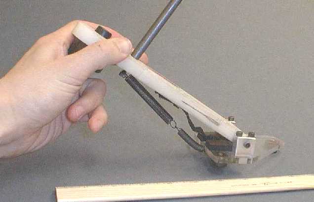
| A prototype of a foot design. The foot has a passive
toe joint. The toe joint is constrained by a limit strap which defines the
maximum flexion angle and a spring which returns it to flat when unloaded. It
is sized after a 50th percentile human foot. It has four contact points. One at
the heel and three points in the toe area. This might seem overconstrained but
if the roll degree of freedom is force controlled the foot will flatten
itself.
|
| 10.98 |
|
| A Preliminary CAD Assembly of the robot M2. Assmebly
is missing many details but contains all the major elements of the robot
design. The actuators in this assembly are an integral part of the leg
design. The actuator and legs share common structural elements. There is a six
axis loadcell in the foot just below the ankle. The hip is just short of one
meter high. There are four actuators in the body(hip yaw & roll) and four
actuators in each leg: hip pitch and knee pitch in the thigh, ankle pitch and
roll in the shin.
|
| 09.10.98 |
|
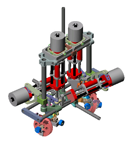
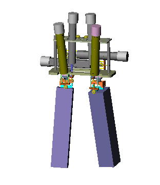
| A possible hip actuation scheme. There are six
linear series elastic actuators within the body of the robot. The blocks are
meant to represent the thighs of the robot. The two vertical actuators in the
foreground actuate the hip pitch(flex/extension). The two vertical actuators
slightly in the background actuate the hip roll(ab/adduction). The two
horizontal actuators actuate the hip yaw. The ordering of the axes is yaw, roll
and then pitch. The yaw and roll axes are essentially a universal joint. The
pitch axis is about 1" below the roll axis.
|
| 08.18.98 |
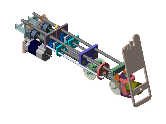
|
| The Leg-uator. A preliminary model of the shin and
foot of the robot. The assembly is slightly incomplete so don't take it
literally. There are two actuators side by side in the shin of the robot. The
actuators share a frame with each other and the leg. The frame consists of
three carbon fiber tubes. The actuators have a motor, belt drive, ballscrew,
and springs on the axis of the ballscrew. The actuators drive cables on a
offset axis universal joint(thru additional carbon fiber tubes, only shown on
one side). Below the universal joint is a six force/torque load cell to measure
the ground contact forces on the foot.
|
?'s. email leinad AT ai DOT mit.edu