
ABSTRACT
The design and analysis of a series of linear actuators based on polymer hydrogel is presented. The actuators use arrays of pH sensitive gel fibers together with a fluid irrigation system to locally and rapidly regulate the composition of the solution. A dynamic model is constructed for one of the linear actuators, which includes the polymer gel, fluidic system, and transmission mechanics. Emphasis in the design and mechanical modeling of the actuators is placed on the complete system including not only the polymer gel, but also on the containment system, irrigation scheme, and servo valving system.
INTRODUCTION
Polymer hydrogels exhibit large, reversible volume changes in response to various external stimuli, such as temperature (Hirotsu, 1987), pH (Kuhn, 1950), solvent (Ohmine, 1982), and electric field (Tanaka, 1982). It has been suggested that these gels could be used as the basis for a compliant actuator or ``artificial muscle.'' Research on gel based actuation has focused on the material itself, including studies of the mechanical properties (Chiarelli, 1988), equilibrium volume (Li, 1989), and mechanochemical kinetics (Matsuo, 1988). However, the design of a practical polymer gel actuator requires consideration not only of the material, but also the supporting mechanics, stimulation method, energy storage system, power delivery technique, packaging method, dynamic model, and control system.
In this paper, we describe the design of two complete, self-contained gel based linear actuators. These actuators were constructed with an array of pH sensitive gel fibers together with a integral fluid irrigation system. The gel fibers, prepared from commercially available poly(acrylonitrile) (PAN) filaments, demonstrate rapid contraction rates together with high intrinsic strength. The irrigation system for each actuator was designed to rapidly and simultaneously control the pH throughout the fiber array. Although there are many possible stimulation methods, this paper focuses on the regulation of pH since this produces rapid phase changes in the gel, as well as provides intrinsic chemical energy storage. Techniques for locally and rapidly regulating solvent composition may also serve as a model for other fluidic stimulation systems.
MATERIALS AND METHODS
In this section, we describe two linear actuators based pH stimulation of PAN gel fiber arrays using an integral fluid irrigation system. The first system used a cylindrical design with gel fiber bundles distributed evenly among an array of irrigating Teflon tubes. The second, based on the results from the first system, used a planar array of gel fibers positioned between two fluid reservoirs containing acid and base respectively.
CYLINDRICAL ACTUATOR
The initial actuation system consisted of a cylindrical polymer gel actuator, mechanical linkage, single stage cable transmission, optical joint position sensor, tendon force gauge, passive antagonistic spring, and two servo controlled valves, as illustrated in Figure 1. The sensors and servo valves were interfaced to the computer, as shown in Figure 2. Designed with low friction and inertia, the system included a modular pulley system for variable transmission ratios. Acid and base were alternatively delivered to the gel fiber bundles through an array of perforated Teflon tubes, as shown in Figure 3.

Figure 1. Schematic diagram of the cylindrical gel actuation system. The apparatus was composed of a single mechanical joint, single stage cable driven transmission, passive antagonist spring, optical joint position sensor, tendon force gauges, and servo controlled valves.
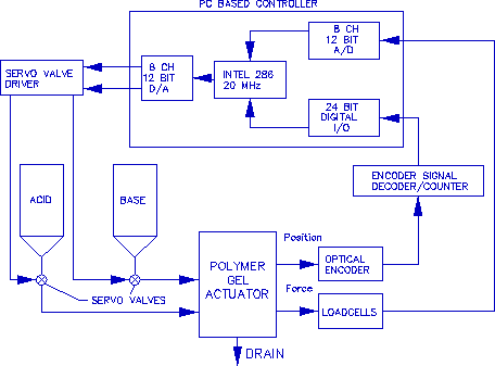
Figure 2. Schematic diagram of the control system.
Gel fiber bundles were prepared from commercially
available PAN fibers (Mitsubishi Rayon Co., Ltd.,
Silpalon 2000/600, 2000 filaments, single filament
diameter: 10 m). The PAN fibers were first
annealed at 210
  C in air for five hours. Four
lengths of the annealed fibers were epoxied to Spectra
tendon (high-molecular weight poly(ethylene), Spectra
1000, Cortland Cable Co., Inc.). The mid section of the
bundles were then saponified in boiling 1N NaOH aqueous
solution for 30 min. Only the middle section was
saponified to prevent swelling and rupture at the
rigid, epoxied terminations. In addition, the
variation of the NaOH fluid level during boiling
produced a continuous region of active to inactive PAN
fiber, creating a smooth stress gradient from swollen
gel to fixed termination, thus reducing fatigue life
failure. The gel bundles with Spectra tendons were
attached to a stationary fixture on one end of the
cylinder and a sliding plate on the other, as shown in
Figure 3. Teflon tubes (1.20 mm O.D., 0.80 mm I.D.)
were perforated with small holes at 1 mm spacing to
serve as the irrigation system. Originally porous
Teflon tubing was used for this purpose, however the
small effective pore size restricted fluid flow. Also,
the high exit velocity afforded by the punctured holes
produced turbulent mixing and a more rapid response
time. Finally, the irrigation tubes were connected to a
fluid manifold, allowing the acid and base lines to be
controlled by two servo valves.
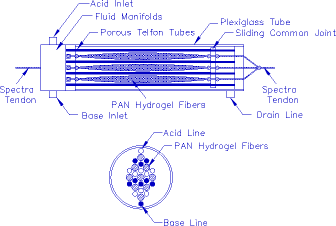
Figure 3. Schematic diagram of the cylindrical polymer gel actuator using PAN gel fibers. Perforated Teflon irrigation tubes were connected to a common fluid manifold allowing only two input lines from the fluid control valves. The distribution of tubes among the fibers attempted to minimize fluid diffusion time to maximize overall actuator performance. The second view shows the arrangement of gel fiber bundles, and acid and base conduits in cross section.
PLANAR ACTUATOR
Based on the results from the first actuator, a second was constructed, which consisted of a planar array of PAN gel fibers situated between two fluid reservoirs containing acid and base respectively, as shown in Figure 4. Two perforated sheets separated the fluid reservoirs from the fiber array, and allowed a controllable simultaneous infusion of fluid onto gel fibers. An additional fluid line into the fiber chamber, provided a continuous flow of neutral solution through the fibers to flush particulate buildup. A common mechanical coupling was constructed to transmit and balance loads from individual fiber bundles. This also prevented cascading fiber failure and simplified analysis by providing equal fiber loading. The mechanical coupling was connected to an instrumented pulley allowing force and position measurement. Acid, base, and neutral lines were regulated using computer controlled servo valves.
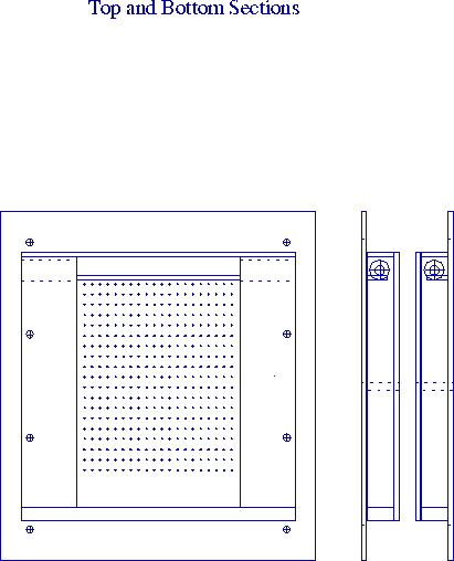
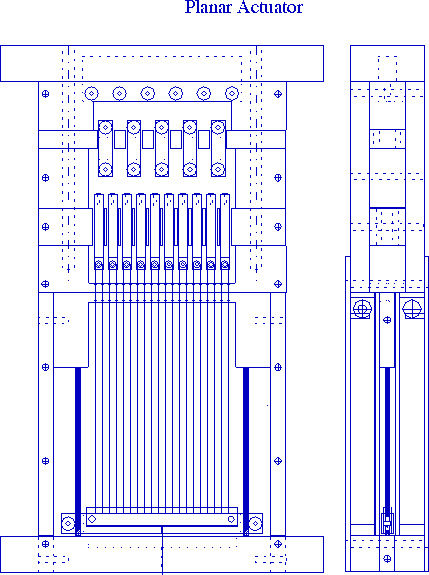
Figure 4. A planar array of PAN gel fibers was positioned between two reservoirs containing acid and base respectively. The reservoirs could alternatively flood the fiber chamber simultaneously through perforated sheets. A common mechanical coupling transmitted and balanced the loads from the individual fiber bundles.
ACTUATOR MODEL
In this section, we describe the analytic model of the planar actuator, including the fluid irrigation system and gel material model. A schematic diagram of the planar actuator is shown below in Figure 5. Fluid flow was modeled using a lumped parameter approach in which individual subunits were assumed identically except for the boundary conditions. Gel mechanics were analyzed using the finite element method to simulate collective diffusion and gel displacement.
Fluid Irrigation System
An individual actuator subunit, shown schematically in Figure 6, consists of five sections: 1. the acid/base (a/b) orifice flow region, 2. a/b entrance region, 3. a/b parallel plate region, 4. w/s mixing region, and 5. w/s parallel plate region.
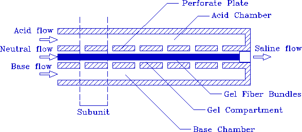
Figure 5. Schematic diagram of the planar actuator.
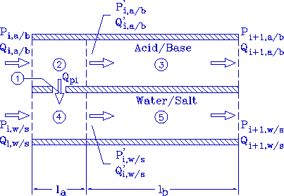
Figure 6. Schematic diagram of an irrigation subunit.
Flow through the orifice was modeled as an inviscid flow with
correction factor  We
assumed flow through a hypothetical surface of area
  within region 2 entered a pore with area
 . This produces the
following equation for flow through the pore,

where I is the fluid inertia

where  is the characteristic length of fluid
travel in region 2, and
  is the length of the
orifice. We assumed
  and
and  ,
thus the flow could be described by

Note that the fluid inertia term is still significant
due to the relatively small  .
.
We assumed that the flow through region 2 toward region
3 was inviscid, and that the inertia was negligible,
since  . Thus the flow through region 2 is
described by

where A is the cross sectional area of fluid flow.
Unlike the flow through region 2, flow through region 4 could not be modeled as inviscid since the incoming orifice flow causes turbulent mixing. We therefore used a control volume approach. The force applied to the control volume is related to the momentum flux of flow by the expression

Assuming the fluid-wall shear force is negligible, we have

where v is the fluid velocity. Since the fluid is incompressible, vA is equal to the flow rate Q. Thus

Making the conventional assumptions about parallel plate flow, the Navier-Stokes equation simplified to

Assuming

the average fluid velocity along the parallel plate in the x direction is described by

Since the fluid is incompressible,  , and
, and

Mass conservation integrates each flow region with

The flow from the fluid reserviors to the actuator inlet ports, and from the actuator outlet ports to the drain were also modeled as inviscid. These flows are described by

for the inlet ports and

for the outlet port, where  ,
,  , and
, and  are the inlet, outlet, and ambient pressures
respectively, and
  and
and  are the inlet and
outlet flow rates. The variables
  is the fluid line
cross section area, and
  the cross sectional
area of the actuator fluid chamber. Note
  and
and
 are related to the subunit flows by
  and
and  , where n is the number of gel fiber
bundles. By conservation of linear momentum,

Given the flow rates  ,
,  , and
, and
 of the mixing compartment, the hydronium
ion concentration of the gel compartment is

where  is the volume of the gel compartment
subunit. The hydroxide ion from base was treated as
 . We assumed complete dissociation of
strong acid/base, though the self dissociation of water
needs to be considered near neutral conditions.
Gel Mechanics
Gel mechanics were modeled using a weighted residual finite element algorithm. A similar theoretical model as that presented in (Segalman et al., 1994) was used in this analysis.
Formulation of a mathematical model that accurately describes the dynamic behavior of the gel requires proper accounting for the swell or contraction of the polymer network, the fluid transfer into and out of the substructure, and the coupled effects between the two phenomena. Also, large deformation kinematics must be used. The interaction between solvent and gel requires the use of two internal state variables to completely describe the system. Complete dynamic model description for small/linear deformations has been offered by (Grimshaw et al., 1990).
The swell of the gel is determined by the rate of solvent absorbed. Assuming no volume change of mixing, this condition becomes

where c is the solvent concentration (mass of solvent
per unit volume of swollen polymer),  is the
volumetric swell of the gel relative to some reference
state, and
  is the density of the pure solvent.
The time derivative above is the ``material
derivative'' --- the derivative of states associated
with particles rather than positions.
The velocity of the solvent is that of the gel plus the
differential velocity due to diffusion. The diffusion
is driven by osmotic pressures which are themselves
functions of two internal coordinates or states:
solvent concentration, c, and the concentration of
 ions, H. Equivalent measures of these
quantities are the mass fractions of gel which are
solvent,
  , and hydrogen ions,
  . (The
mass fraction of polymer is simply calculated as
 .) It is these two quantities as
well as the displacement components of the gel which
are used as primary variables in this exposition.
The solvent concentration can be represented in terms of a mass fraction by

where  is the density of pure polymer.
For a system of three components (polymer, solvent, and
hydrogen ions), there are two independent diffusion
equations, each depending on the the gradients of at
most two of the components. The isothermal diffusion
equation describing the evolution of the solvent mass
fraction,  is
is

where the terms  are diffusivities, and
 represents spatial gradient.
Because the above evolution equation is written in a
frame moving with the gel, the convective term is
different from that in the Eulerian formulation.
Derivation of this equation requires exploitation of
the continuity equation, Eq 1.
The transport of  is similar to that of solvent, but it also
involves a source term

where  accounts for creation or neutralization of H.
Note that through
  ,
,
 is a tunable parameter
that may be varied through electrical or chemical means. Also note
the modification to the convective terms resulting from formulation
of the equations in a frame that convects with the gel.
The stress relationships for large deformation elasticity
require the use of large deformation strain quantities. The
deformation gradient  is defined as
 where
where  is the location of the particle in the unstrained
state. In this problem, it is useful to factor the deformation
gradient into its unimodular part and a part representing isotropic
swell,

where
 and
and  is the volumetric swell of the gel.
For a solvent-concentration dependent neo-Hookean type solid, the Cauchy
stress,  , resulting from a given deformation is

where

G is the shear modulus, and p is a Lagrange multiplier dual to the incompressibility constraint on the swollen polymer. Because of the assumed incompressibility of the gel/solvent system, the above equation presents stress only up to an unknown pressure. The incompressibility condition on the swollen polymer is simply a statement that the volume of the material is not a function of the imposed pressure.
The conservation of momentum for the gel is

where  contains all local body forces, such as gravitational
or electromagnetic loads.
The governing differential equations are transformed into a system of algebraic equations through a standard Galerkin-finite element formalism. However, because of the Lagrangian formulation, all interpolation is over a material manifold rather than over space. The above process is reasonably standard, however, care should be taken to use the chain rule in evaluating spatial derivatives:

A sequential solution strategy was chosen to solve the system of equations. First, the mass transport equations were solved and then these results were piped into the elasticity relationships to calculate the resulting expansion/contraction.
RESULTS AND DISCUSSION
CYLINDRICAL ACTUATOR
The performance of the cylindrical actuator is shown in Figure 7. Using a simple bang-bang control scheme, the arm rotated from zero to 170 degrees and back in approximately 45 seconds, generating a maximum tendon tension of 0.35 N. Although the cylindrical design achieved our goal of a complete, self-contained polymer gel actuator, there were a number of areas in which performance was be improved in the subsequent design. First, the irrigation scheme was not optimal in that fluid from the upper tubing flowed over the lower fibers, thus wasting fluid in the lower region. In the planar design, fluid traveled along the length of the fiber, optimizing the use of the solution. Second, the swollen fibers in the cylindrical actuator pressed against the adjacent tubes, thus blocking the pores. In this state, fluid flowed only from the extreme ends of the irrigating tubes, which delayed the onset of contraction. The planar design separated the fiber bundles from each other and from the inlet pores. Third, uneven fiber loading resulting from differential phase change across the array, creating unwanted side loading on the transmission, as well as reducing fiber fatigue life. In the subsequent design, a mechanical transmission was added to equalize the force across the fiber array. Fourth, particulate buildup from the acid/base reaction impeded fiber mobility. The planar actuator provided a continuous neutral flow through the fiber region to flush the reaction products. Finally, the planar system provided a simpler and more consistent system for mechanical modeling.
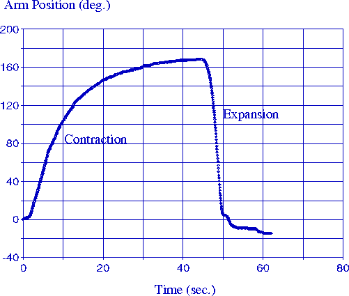
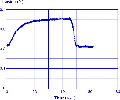
Figure 7. Contraction and expansion is shown using a passive spring as an antagonistic element. The arm rotated from zero to 170 degrees and back with the maximum tendon tension was 0.35N. Maximum arm speed during contraction was approximately 16 degree per second.
PLANAR ACTUATOR
In this section, we present and discuss the results of
the planar actuator simulation and experimental data.
Simulated pore flow rate  and hydronium ion
concentration cH for individual actuator subunits is
shown in Figure 8. Identical pore diameters were
initially used to produce identical orifice flow rates;
however the hydrogen ion concentration varied in the
fiber chamber, as fluid from upstream pores mixed with
fluid in downstream regions. A more uniform uniform pH
gradient was produced by decreasing the hole size along
the flow direction. This produced uneven orifice flow
rates, but more homogeneous hydrogen ion concentration,
as shown in Figure 8.
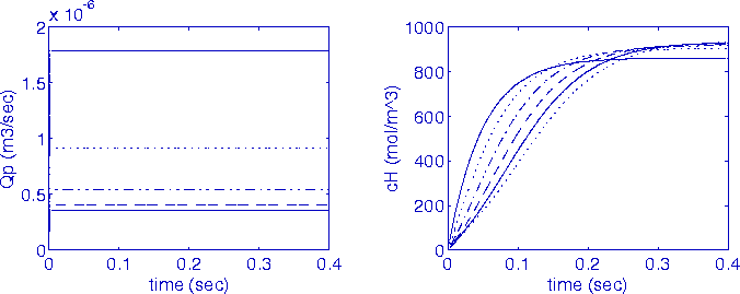
Figure 8. Decreasing orifice diameters produce more a uniform hydrogen ion concentration along the fiber. Different line types are used to represent flow and ion concentration for the six different actuator subunits. In order upper to lower subunits in the fluid flow direction: ---, ..., -...- - - -, ---, and ....
Calculations were performed for gel fiber subject to
the pH history as calculated above. These calculations
were performed using a simplified mesh, as shown in
Figure 9. Actual calculations were performed on a small
section ( ) of the fiber, since pH was
assumed uniformity for each small actuator subunit.
Also, due to symmetry only one half of the fiber was
modeled axially. The deformed mesh associated with the
long-time immersion of the gel fiber in a low-pH
environment is shown in Figure 9b. Figure 10a shows
the gel displacement versus time assuming each fibril
in the fiber bundle is subject to an identical pH
environment, as calculated in the previous section.
Figure 10b shows the simulation results assuming the
gel bundle functions effectively a single, large fiber.
The cusp in this plot is due to the relatively coarse
finite element mesh.
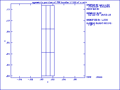
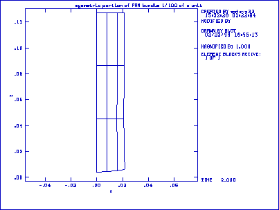
Figure 9. Finite element mesh. The figure to the left shows the initial, undeformed gel. The figure to the right shows the gel after immersion in low pH. Note the initial greater contraction on the anterior surface of the gel (left side).
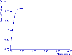
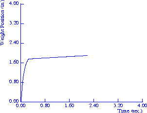
Figure 10. Assuming an identical pH environment for each fibril of the fiber bundle, gel displacement is rapid, as shown to the left. However, assuming the fiber bundle functions effectively as a single, large strand, the response time is greatly reduced, as shown to the right.
Experimental data from the planar actuator are shown in Figure 11. The response time of the actual system was far slower than the simulated system which assumed an identical pH environment for all fibrils, as shown in Figure 10a. The simulation which assumed the bundle functions as a single, large fiber, however, produced a slower overall contraction rate. Given that the pH environment changes an order of magnitude faster than the experimental system, and that the individual fibril response time is on the order of 0.1 to 0.2 seconds, it appears the fiber bundle under tension impedes diffusion of its interior members, and that further actuator improvement requires separation of the individual fibrils. Future work will therefore be directed toward individual fiber actuation systems, as well as mechanical designs which more quickly irrigate throughout the fiber bundle.
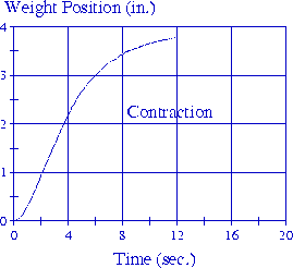
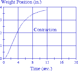
Figure 11. Contraction and expansion response times are improved with the planar actuator.
CONCLUSION
In this paper we describe the design and construction of two polymer gel actuation systems based on the irrigation of gel fiber arrays using acid and base solutions. A dynamic model of a planar actuator was presented which included the fluid irrigation system and gel mechanics. Although actuator response time was improved by more careful attention to irrigation flow, balanced gel loading, and fiber bundle separate, initial results suggest further improvement may be realized by individual fibril irrigation.
ACKNOWLEDGMENTS
Support for the research at the Artificial Intelligence Laboratory was provided by Sandia National Laboratory under contracts numbers AI-3367 and AA-9823, and support for research at Sandia National Laboratory was provided by the U.S. Department of Energy under contract number DE-AC04-94AL85000. The authors would also like to thank a dedicated group of undergraduate researchers: William Lee, Amber Duelley, Yueh Lee, and Thanh Pham.
REFERENCES