 |
 |
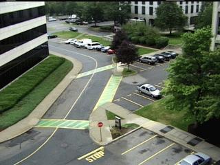
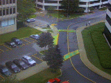
We tackle the problem of self-calibration of multiple cameras which are very far apart. For example, we are given two views of a parking lot. We wish to determine the areas of overlap between the views so that we can uniquely identify the same object moving in both views and establish the trajectory of the object in a common global coordinate frame.
|
|
|
Given a set of feature correspondences one can determine the camera geometry. The key problem we address is finding such correspondences.
What makes this problem hard?
Since the camera geometry (location and orientation) and photometric characteristics vary considerably between images one cannot use brightness and/or proximity constraints. Instead we propose a three step approach:
We do not assume synchronized cameras. Enforcing the geometric constraints enables us to align the tracking data in time.
 |
 |
 |
 |
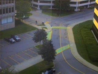
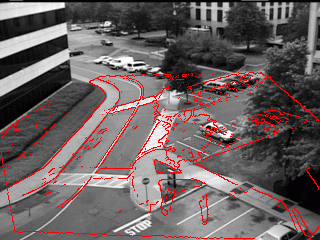
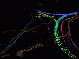
Using the tracking data we produce a rough planar alignment (homography). We can then warp the first image towards the second.
 |
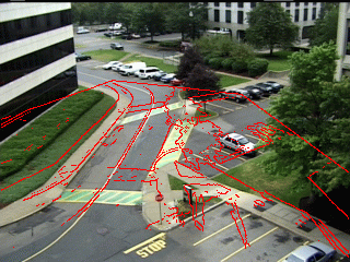 |
Note the residual alignment errors when we overlay the edges from the warped image onto the second image. This is due in part to fact that the tracked objects do not lie exactly on the ground plane but on a plane parallel to the ground and one meter above it.
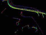
Starting with the rough alignment we refine the alignment using the greayscale images. we use robust direct-methods for planar alignment. The result still show some misalignment. The reason for that is still under study.
 |
Point correspondences which do not lie on the ground plane can be used
to determine the epipole geometry. For this we can use the tracked
object coordinates because, as we have seen, they do not lie exactly
on the ground plane. Given the homography matrix of the ground plane,
![]() and the homgraphy matrix of the points,
and the homgraphy matrix of the points, ![]() ,
one can compute the epipole e':
,
one can compute the epipole e':
| (1) |
We can also compute ![]() which is the projection of the 'line at
infinity' in the image:
which is the projection of the 'line at
infinity' in the image:
If the internal camera parameters are know, then we can determine the overhead view of the groundplane which will allows us to align our site model to aerial photographs and recover the true velocity, up to a scale, of tracked objects.
As input we using tracking data from the 3 north facing cameras of our site.
 |
 |
 |
 |
 |
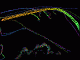 |
Using the tracking data we peform geometric alignment of the images and the tracks.
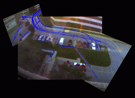 |
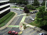
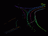
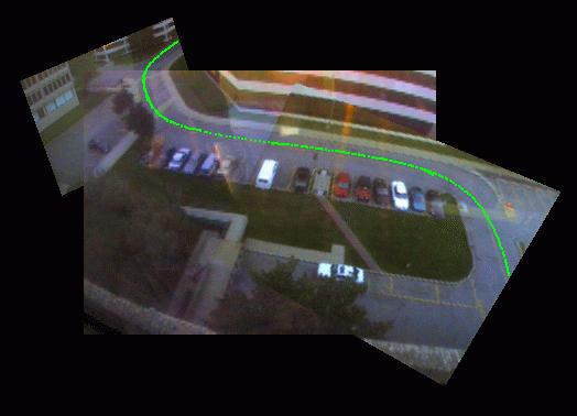
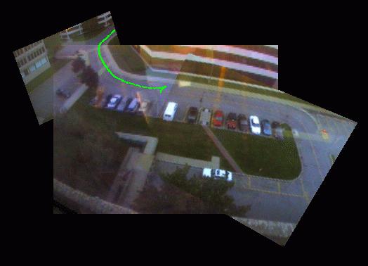
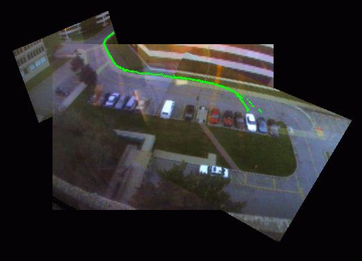
After geometric alignment of the tracks we can combine tracks from multiple views into a single track. These are examples of multiple track segements determined to belong to the same object. (Images are shown in low resolution. Click on images for full size images. Click on App for Java Applet)
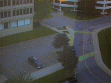
 Images/snap4.s.jpg the parking lot. App. |
 Images/snap7.s.jpg the parking lot. App. |
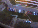
 Images/snap3.s.jpg parking spot and leaves top left. App. |
 Images/snap2.s.jpg meet up and walk together. App. |
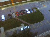
 Images/snap1.s.jpg cars were combined together. App. |
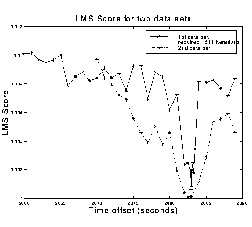
The cameras are not synchronized but we can determine the time offset between the cameras (i.e. synchronize the cameras) by noting that when we have the correct offset the homography mapping is a good model and the Least Median of Squares (LMedS) error is small. For an incorrect offset the LMedS error is large. We can therefore perform a one dimensional search for the correct offset.
 |
While object tracks as seen from multiple cameras are now combined, they remain in an image-dependent frame, thus making comparison of moving objects' speed and direction difficult. In a typical urban outdoor scenario, objects such as people and cars move in a common ground plane. Thus the ground plane is a natural basis for establishing a global coordinate system independ of image coordinate frames. Transforming the tracks observed by multiple cameras from image coordinate frames into the common ground plane coordinate frame sets the stage for global analysis of activities in a scene
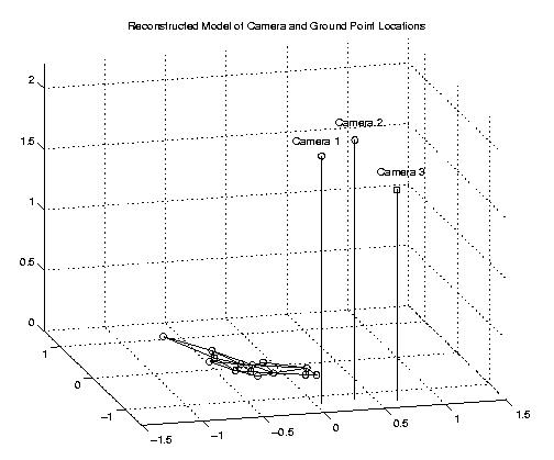
Using 3 cameras and nominal information about the internal parameters of these cameras, we are able to recover the unique 3D location and orientation of the cameras relative to the ground plane.
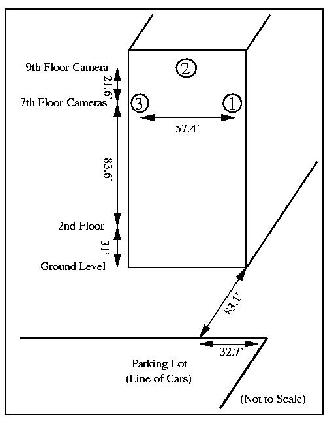 |
 on the ground plane are landmarks with known distances. |
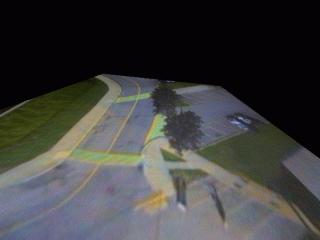
The recovered 3D location and orientation of the cameras can be used to reconstruct an overhead view of a ground plane.
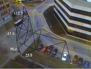 with known distances. Note the foreshadowing of distances caused by the camera being at an angle from the ground plane. |
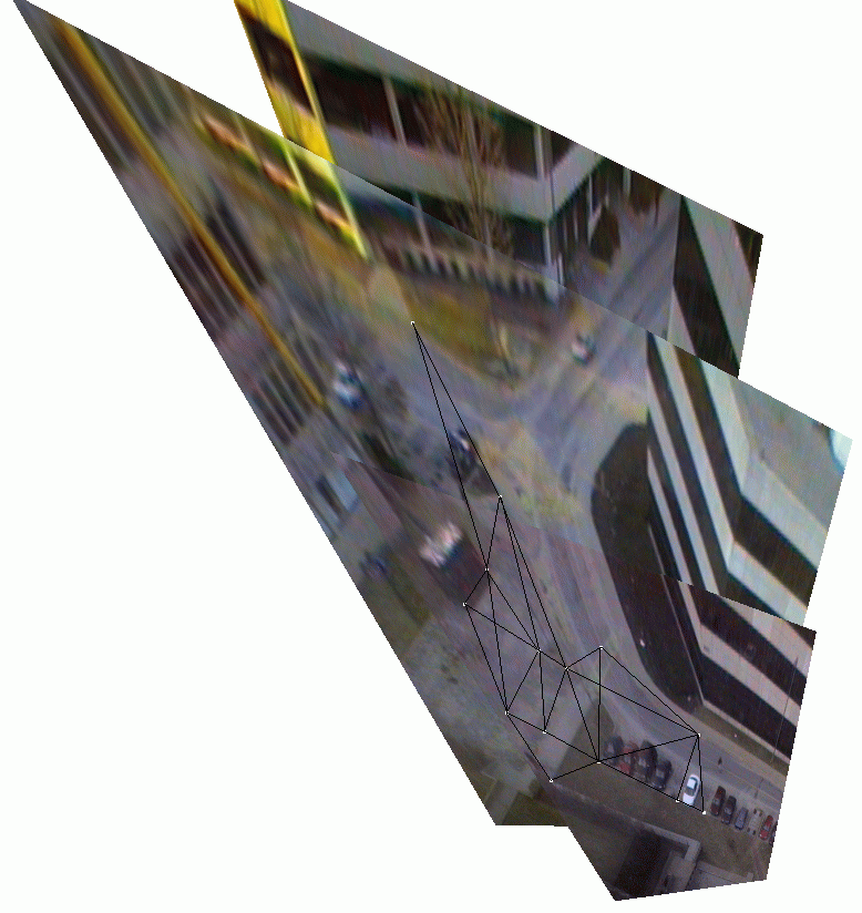 views. The relative distances on the ground plane are now much more realistic. |