Dynamic Oscillators for Motor Control |
||
| Dynamic Oscillators: MIT Artificial Intelligence Laboratory 545 Technology Square, #920 Cambridge, MA 02139 |
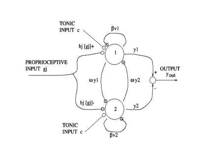
Schematic of the oscillator. Black circles correspond to inhibitory connections,open circles to excitatory. The vi connections correspond to self-inhibition, and the yi connections give the mutual inhibition. The positive and negative parts of the input gj are weighted by the gain hj before being applied to the neurons. The two outputs yi are combined to give the oscillator output yout.
Neural oscillators have been used to generate repetitive arm motions. The cou-pling between a set of oscillators and the physical arm of the robot achievesmany different tasks using the same software architecture and without explicitmodels of the arm or environment. The tasks include swinging pendulums attheir resonant frequencies, turning cranks, and playing with a slinky.Using a proportional-derivative control law, the torque at the ith joint canbe described by:
where ki is the stiffness of the joint, bi the damping, thetai the joint angle, and thetavi the equilibrium point. By altering the stiffness and damping of the arm, thedynamical characteristics of the arm can be changed. The posture of the armcan be changed by altering the equilibrium points (Williamson 1996). This typeof control preserves stability of motion. The elastic elements of the arm producea system that is both compliant and shock resistant, allowing the arm to operatein unstructured environments.Two simulated neurons with mutually inhibitory connections drive each armjoint, as shown in Figure 6. The neuron model describes the firing rate of a biological neuron with self-inhibition (Matsuoka 1985). The firing rate of each neuron is governed by the following equations:
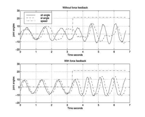
where xi is the firing rate, vi is the self-inhibition of the neuron (modulated bythe adaption constant beta), and omega controls the mutual inhibition. The output ofeach neuron yi is the positive portion of the firing rate, and the output of the whole oscillator is yout. Any number of inputs gj can be applied to the oscillator, including proprioceptive signals and signals from other neurons. Each inputis scaled by a gain hj and arranged to excite one neuron while inhibiting the other by applying the positive portion of the input ([gj]+) to one neuron and the negative portion to the other. The amplitude of the oscillation is proportional to the tonic excitation c. The speed and shape of the oscillator output are determined by the time constants tau1 and tau2. For stable oscillations, tau1/tau2 should be between 0.1 and 0.5. The stability and properties of this oscillator systemand more complex networks of neurons are analyzed in Matsuoka (1985) and Matsuoka (1987).The output of the oscillator yout is connected to the equilibrium point thetav. One neuron flexes the joint and the other extends it about a fixed posture thetap,making the equilibrium point thetav = yout + thetap. The inputs to the oscillators areeither the force (tau) or the position (theta) of the joint.The interaction of theoscillator dynamics and the physical dynamics of the arm form a tightly coupleddynamical system. Unlike a conventional control system, there is no \set-point"for the motion. The interaction of the two coupled dynamical systems determinesthe overall arm motion.The oscillators have two properties which make them suitable for certaintypes of repetitive motions. First, they can entrain an input signal over a widerange of frequencies. In the entrained state, the oscillator provides an output atexactly the same frequency as the input, with a phase di_erence between inputand output which depends on frequency. Second, the oscillator also becomesentrained very rapidly, typically within one cycle. Figure 7 shows the entrainmentof an oscillator at the elbow joint as the shoulder of the robot is moved. Themovement of the shoulder induces forces at the elbow which drive the elbow insynchrony with the shoulder. Slinky: The entrainment property can be exploited to manipulate objects, suchas a slinky. As the slinky is passed from hand to hand, the weight of the slinkyis used to entrain oscillators at both elbow joints. The oscillators are completelyindependent, and unsynchronized, in software. With the slinky forming a physi-cal connection between the two systems, the oscillators work in phase to producethe correct motion. The adaptive nature of the oscillators allows them to quickly recover from interruptions of motion and changes in speed. An example of the coordination is shown in Figure 8.
Entrainment of an oscillator at the elbow as the shoulder is moved. The jointsare connected only through the physical structure of the arm. Both plots show theangle of the shoulder (solid) and the elbow (dashed) as the speed of the shoulder ischanged (speed parameter dash-dot). The top graph shows the response of the armwithout proprioception, and the bottom with proprioception. Synchronization occursonly with the proprioceptive feedback. recover from interruptions of motion and changes in speed. An example of thecoordination is shown in Figure 8.Cranks: The position constraint of a crank can also be used to coordinate thejoints of the arm. If the arm is attached to the crank and some of the joints aremoved, then the other joints are constrained by the crank. The oscillators cansense the motion, adapt, and settle into a stable crank turning motion.In the future, we will explore issues of complex redundant actuation (such asmulti-joint muscles), utilize optimization techniques to tune the parameters ofthe oscillator, produce whole-arm oscillations by connecting various joints into asingle oscillator, and explore the use of postural primitives to move the set pointof the oscillations.
|
|
Representatives of the press who are interested in acquiring further information about the Cog project should contact Elizabeth Thomson, thomson@mit.edu, from the MIT News Office, http://web.mit.edu/newsoffice/www/ . |
||